SAVE BIG!
To celebrate Columbus Day, we are offering all PreciseLOOP antennas at a BIG discount. Hurry, order right away. This sale is limited to the first 30 customers.
SAVE BIG!
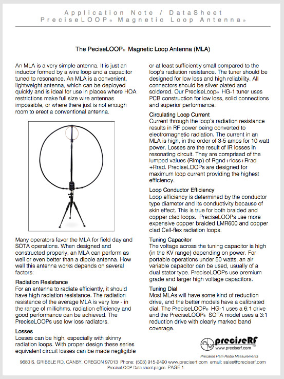
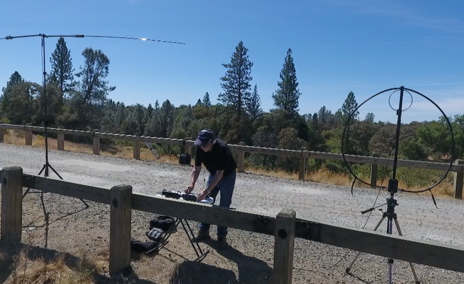
In response to a number of inquiries from our customers, we have published an appnote covering the new PreciseLOOP antennas. In addition to a technical description, it also gives detailed information of the PreciseLOOP specifications.
Among the topics covered are maximizing gain, radiation patterns, loop current, SWR plots, comparisons to the dipole antenna, set-up and use and internet discussions. In makes an excellent adjunct to those using any loop antenna or to those considering buying one.
73,
Roger
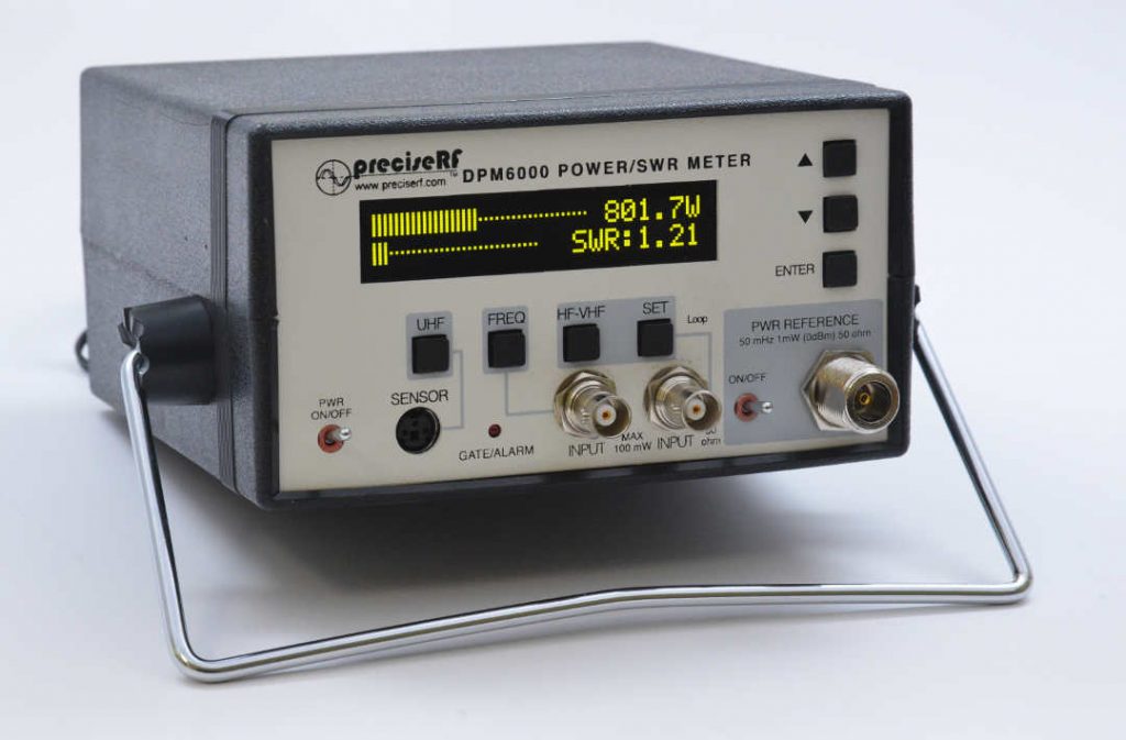
Users of the popular DPM6000 Power Meter may have their unit upgraded FREE with new firmware (V2.40) and a minor mod in the log amplifier module to improve the frequency response flatness.
Units shipped prior to 9/1/17 only specified the frequency range (50KHz to 500 MHz) but not the frequency response. With this mod the frequency response can now be specified as: +/- .5 dB from 50KHz to 250MHz for the FWD and REFL direct inputs.
To arrange your upgrade, please contact Audrie Crane from sales. We will pay shipping both ways (standard USP postage). We are committed to provide you the best possible products and thank you for your valuable feedback.
73,
Roger
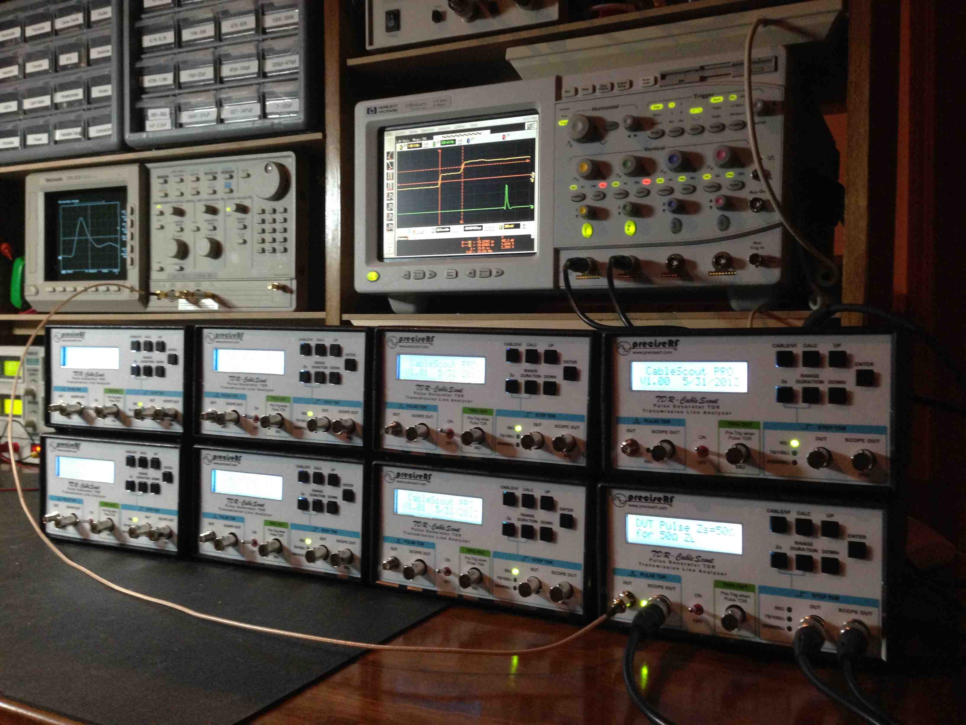 Our latest manufacturing run (manufactured in the USA) of our popular TDR pulse generator now features individualy calibratd TDR pulse data and pulse outputs rise times times under 150 ps. Each unit in this manufacturing run calibrated and performed better than our published specifications. Feedback from current users has been positive, and no firmware upgrades are required.
Verify your transmission line quality and measure losses
In addition to measuring the actual cable impedance of your transmission lines, a feature especially popular is the ability to measure cable losses in dB per hundred feet. The fast rise time and narrow pulse width allows loss measurement by analyzing GHz harmonic contents and converting this signal into pulse integration using an ordinary 200 MHz oscilloscope. The TDR computer compares the input pulse to the output pulse given a known cable length and computes the loss in dB/100 feet at 100 MHz. While there are a number of 50 ohm cables for example, not all cables have identical losses. With the loss measurement feature, hams can verify their cable impedance with as little as a 12″ cable sample. See our video on making TDR cable measurement..
Those hams with older Tektronix sampling scopes can take advantage of the TDR pulse generator fast rise time by using the 100 ns pre-trigger output and as a result can view the leading edge of the pulse TDR waveform and achieve a stable display.
 Calibration verification
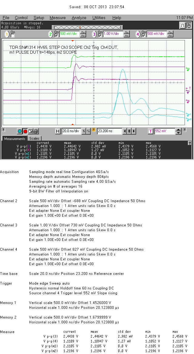
For accurate and consistent results, Ham radio operators and experimenters rely on their test and measurement equipment accuracy. When making transmission and feed line impedance measurements step and pulse performance is especially important. Now, in addition to specifications published on our data sheets, each new TDR pulse generator is delivered with a comprehensive five channel display characterizing the each output from the TDR pulse generator.
In addition to measured values the calibration now includes actual values and statistical data such as mean, standard deviation, minimum and maximum values. Rise time performance is measured down to the picosecond level. Click on the image to view in greater detail.
![]() We are excited with the launch of the PreciseRF YouTube channel. The first in a series of application videos is the TDR Tutorial Video. Our customers wanted video instruction and demonstration. For this production the foundation of this new video came from our application notebook. This new video running time is 23 minutes. It covers the basics of TDR applications and a detailed demonstration of the popular TDR CableScout.
We are excited with the launch of the PreciseRF YouTube channel. The first in a series of application videos is the TDR Tutorial Video. Our customers wanted video instruction and demonstration. For this production the foundation of this new video came from our application notebook. This new video running time is 23 minutes. It covers the basics of TDR applications and a detailed demonstration of the popular TDR CableScout.
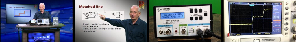
Step-by-step demonstration cover:
Aurora, Oregon
PreciseRF published a new application note entitled “Using TDR for Measuring Transmission Lines in Ham Radio Installations”
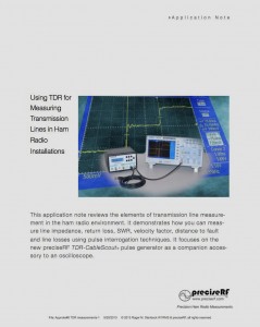 This application note reviews the elements of transmission line measurement in the ham radio environment. It demonstrates how you can measure line impedance, return loss, SWR, velocity factor, distance to fault and line losses using pulse interrogation techniques. It focuses on the new preciseRF TDR-CableScout® pulse generator as a companion acces- sory to an oscilloscope.
This application note serves as a tutorial and review of TDR measurements and as a user guide for the TDR-CableScout®. Included are step-by-step instructons on how to use it with your oscilloscope. Topics include transmission line faults and how to locate them, reflection coefficient, return loss, SWR, cable impedance (Zo) measurements, distanced to fault (DTF), velocity factor (VF) and line loss measurements.
![]() Application note entitled “Measuring Return Loss with an oscilloscope and a Return Loss Bridge (RLB)” has been completely re-written. We expanded and made corrections to this application note. There existed some confusion as to the definition of “return loss” particularly whether it is a positive or negative quantity. Also improved is the step-by-step procedure on how to measure return loss in every day ham radio applications.
Application note entitled “Measuring Return Loss with an oscilloscope and a Return Loss Bridge (RLB)” has been completely re-written. We expanded and made corrections to this application note. There existed some confusion as to the definition of “return loss” particularly whether it is a positive or negative quantity. Also improved is the step-by-step procedure on how to measure return loss in every day ham radio applications.
We thank our customers who gave us their valuable time in providing us feedback. Without their help the improvements would have been more difficult. We encourage all our customers to contact me here at PreciseRF with their recommendations and any feedback which will improve our products. We advertise and support eHam and QRZ. Reviews on either site will help other hams select products for their ham radio activities.
Happy New Year,
73
Roger W1RMS
 A new low level detecter provides QRP (low power) demodulation with high linearity at 100% modulation levels. This unique bias scheme is entirely passive and does not require an external power source. This new circuit was developed by the design team at the W1RMS labs.