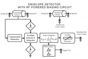
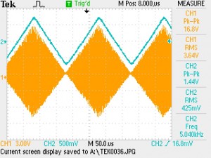
On November 29th 2011, the Unites States Patent and Trade Mark Office (USPTO) notified PreciseRF that it acknowledged receipt and disclosure of a new invention entitled ENVELOPE DETECTOR WITH RF POWERED BIASING CIRCUIT and accordingly, this new invention is entitled to patent protection under 35 U.S.C. 111, including establishing the invention filing date and authorizing marking its products “PATENT PENDING”
In a statement, Roger M. Stenbock of W1RMS and chief engineer at PreciseRF, praised his team. “We take great pride in our engineering team’s innovation and look forward to include this invention in new products scheduled for introduction early 2012 serving the ham radio marketplace”
A brief overview of the specifications include:
BACKGROUND
The present invention relates to a system, method, and device for envelope detection with RF powered biasing circuits, and more specifically to passively detecting the envelope….
SPECIFICATIONS:
As will become apparent in the specifications, this method overcomes some of the limitations, such as significant base band inter modulation distortion 10 (IMD) products and errors in trapezoid and two-tone test analysis, inherent in un-biased envelope detectors at low signal levels. A detailed circuit description follows a discussion of the invention…
The method according to the present invention consists of a circuit that is an essential component of a station monitor which monitors RF transmitter emissions of amplitude modulation (AM), double side band (DSB) and single side band signals (SSB). It includes an RF sampler and envelope detector. It can be used for both QRP (low power) and QRO (high 5 power) operation. The station monitor allows for precise examination and tuning of the entire RF transmitter chain. This chain may include transceiver outputs ranging from about 0.1 to 100 Watts driving linear RF amplifiers. In addition to a wide band sampler, the station monitor includes a high performance demodulator, a variable base band output and an oscilloscope trigger output. This invention features a passive diode biasing circuit for detecting very low (QRP) transceiver envelope Levels.
NON-BIASED ENVELOPE DETECTORS: Low cost passive wide band demodulators employ an envelope detector. This detector is an electronic circuit that takes an RF signal as input and provides an output that contains the “envelope” of the original signal. Generally, a diode rectifies the incoming signal, allowing current flow in only one direction. Practical envelope detectors use either half-wave or full-wave rectification of the signal to convert the AC audio input into pulsed DC signals. Filtering is then used to smooth the final result. This filtering is rarely perfect and some “ripple” is likely to remain on the envelope output, particularly at low frequencies. More filtering gives a smoother result, but decreases the responsiveness; thus, real world designs must be optimized for the application.
LOW LEVEL DETECTION: Another undesirable characteristic is non-linearity of the detected base band. This is caused by the diode’s conduction voltage drop ranging from about 0.2 volt to 0.8 volt (forward bias voltage drop) depending on the diode type and current. In the forward bias voltage diminished conduction region the diode does not linearly detect.
For high level RF envelopes, this region usually represents only a small percentage of the envelope and can be ignored. However, in low level RF envelopes encountered with QRP operation, this region represents a considerable portion of the modulation envelope. As a result, the base band will exhibit significant non-linearity near the maximum modulation depth of the RF envelope.
One way to mitigate this undesirable characteristic is to bias the detector such that it is conducting throughout 100% of the modulation envelope. The present art effectively accomplished this by means of a precision current source using a separate power supply. Unfortunately this adds complexity and cost.
This invention overcomes these shortcomings by incorporating a novel way to achieve such bias current (100-500uA). The current is derived from the RF signal by a second detector, with a proprietary circuit (this invention) which is passive and does not require an external power source. This results in embodiment with lower cost and reduced complexity, wilts providing exceptional base band linearity over a wide input range for precise transmitter amplifier performance measurements.


